Add LEDs To Everything
Over the last few days I had been putting together a lighting rig for my NobleChairs HERO, intending to make a tilt/spin controlled lighting effects unit that could be non-destructively fit to the botto of my chair. However I need parts and laser cut doodads and- well- lockdown isn’t helping with that.
So… While my NobleChairs build is on haitus I decided to take everything I’d learned from putting it together and writing the code and apply it to my son’s ride on car!
Before you continue, be warned: this is brief overview to inspire you to build your own, and not a full set of instructions.
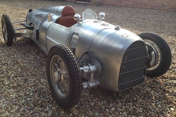
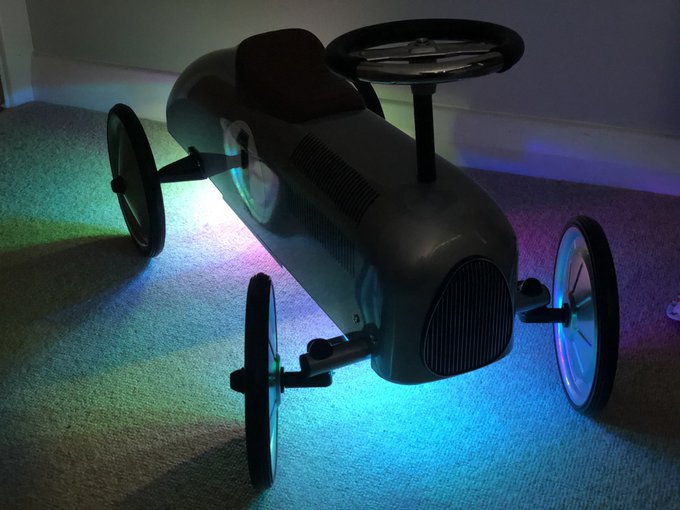
Also very clearly inspired by the Auto Union Grand Prix cars: pic.twitter.com/vnP22VmCkD
— Phil Howard (@Gadgetoid) June 27, 2020
Being built from a solid steel or aluminium shell with plenty of room inside and a reinforcing plate along the bottom for mounting things makes it an absolute prime target for mods and hacks. While motorising was my first thought, I lack the necessary skills, equipment and patience to really make that happen. Lights was the next best thing.
But first, let’s just stop and admire what must have been the inspiration for this toy – that vintage Grand Prix Auto Union racer. What a thing of beauty!
With anything I build I like to be as non-destructive as possible, retaining parts for future builds (when I get bored of the old ones) and non damaging the thing I’m modifying if I can possibly help this. This frugality and determination can often stall my projects and was the death of my Rasberry-Pi-in-a-MegaDrive build:
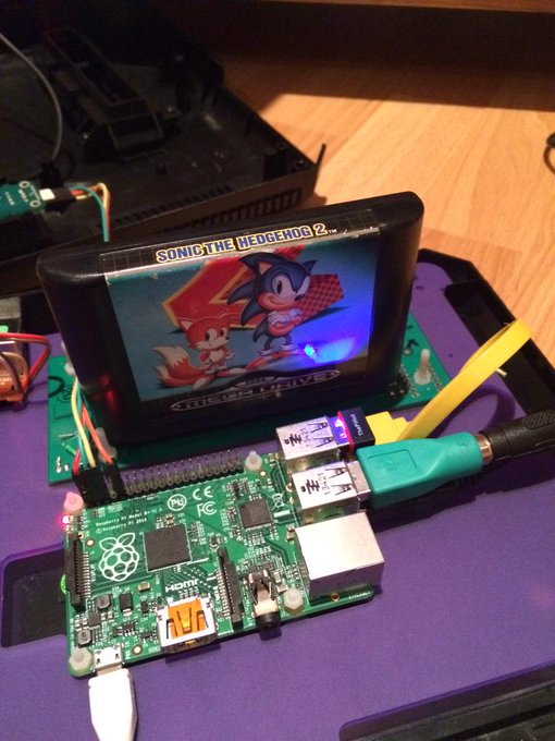
😀 MegaPi is about to rock some Sonic 2. P.S. If anyone has an unwanted copy of Megagames with Columns on it… pic.twitter.com/bKJGDOddpu
— Phil Howard (@Gadgetoid) June 20, 2015
In this case, however, it was surprisingly easy to fit everything into the car without needing any tools or drastic modifications. Here’s the BOM:
1. A random string of 25 bulb-style WS2811 LEDs (I got these from Ben of Phenoptix fame many years ago)
2. One prototype LED driver board (secrets! sshhhh! though you can usually connect these LEDs directly to an IO pin if you’re brave)
3. One Raspberry Pi Zero W (I recommend a starter kit if you’re new to Pi – https://shop.pimoroni.com/products/pi-zero-w-starter-kit)
4. One Anker PowerCore 15000 Redux (love these, this is the one I bought: https://www.amazon.co.uk/gp/product/B07HBWF1K8)
5. Some sticky cable clips from Amazon (super overpriced way to buy them, but affiliate link here if you need: https://amzn.to/3ihD2BO)
6. Some 3M double-sided sticky pads for mounting the battery (again, overpriced, but mmm affiliate link: https://amzn.to/3icoF1A)
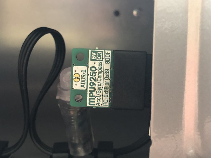
7. (Optional) Some kind of IMU if you want to get fancy (I used a prototype of https://shop.pimoroni.com/products/icm20948)
You’ll need to set up an SD card for your Pi Zero, pre-configured with your WiFi network and with SSH enabled so you can connect to and modify your lighting patterns as you go. Raspberry Pi themselves cover how to do this: https://www.raspberrypi.org/documentation/configuration/wireless/headless.md
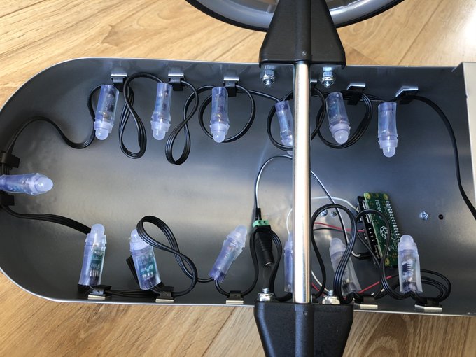
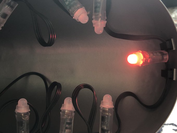
The first step is to tame the tangle of lights and affix them around the inside edge of the car. This was by far the most difficult step of the build, since these lights have too much wire between them, and the wire doesn’t seem to be routed consistently. Using LED strips/tape would make this step MUCH easier.
This would have been so much easier with LED tape! pic.twitter.com/7dsudl3YLS
— Phil Howard (@Gadgetoid) June 28, 2020
The plastic clips I rolled the dice on proved to be more than suitable, and doubling up on them helped tame the LEDs and keep them in place:
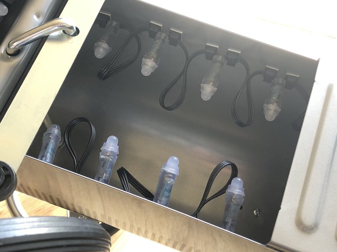
Looking tidier! pic.twitter.com/bHURPxjOZD
— Phil Howard (@Gadgetoid) June 28, 2020
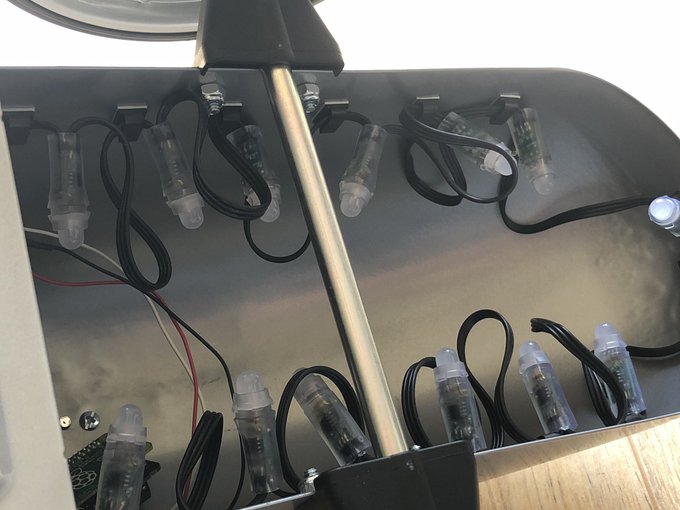
The second step was to find somewhere to affix the Pi. Fortunately the plastic clips made this a breeze, although normally I’d use self-adhesive PCB mounts which are designed to fit through the mounting holes of the PCB rather than awkwardly clip over the edges:
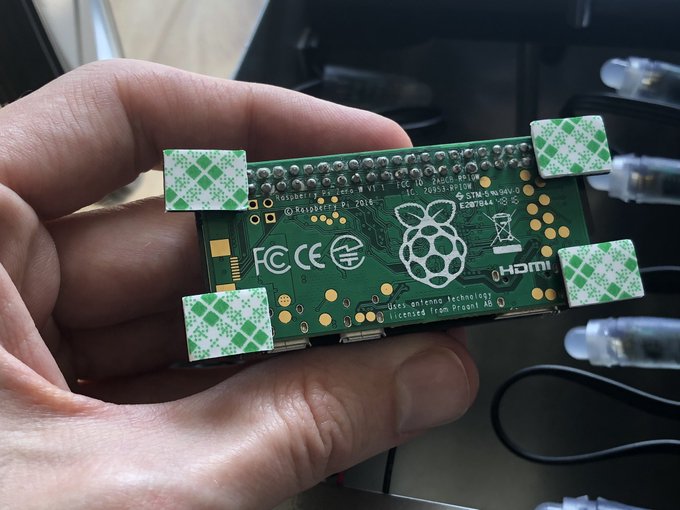
These clips will even hold the Pi Zero! Though in retrospect I’m not sure how the WiFi is getting out of this metal can…. pic.twitter.com/gT2Q9lj2DQ
— Phil Howard (@Gadgetoid) June 28, 2020
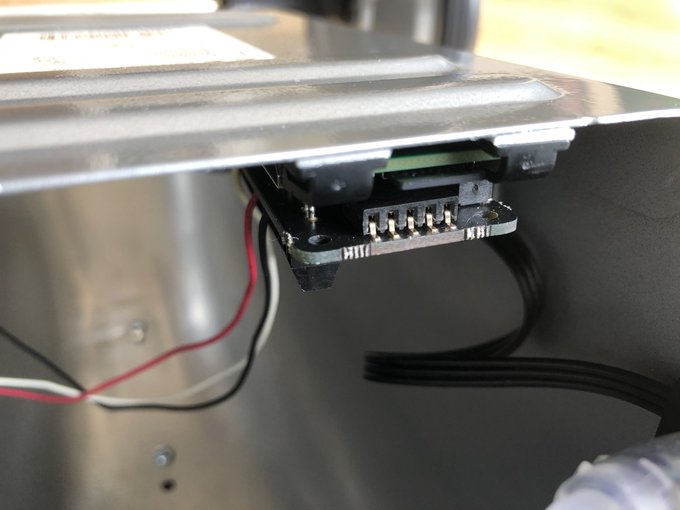
I made sure to position the Pi with the SD card slot accessible, so I could modify the software offline if anything went awry. The optional IMU, mentioned earlier, was plugged into a socket on the LED driver board and allowed me to add some fancy lighting effects to the car.
A strip of 3M tape was all it took to *very firmly* fix the Anker battery to the inside of the car chassis. In future I think I’ll find some self-adhesive velcro pads instead, so the battery is secure but it’s easier to remove it for charging or for swapping into other projects.
Before we get fancy with the IMU-enhanced effects- a simple rainbow test script to verify everything works:

More action in a darker room! pic.twitter.com/WzKypuqCDT
— Phil Howard (@Gadgetoid) June 28, 2020
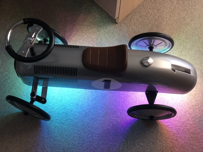
In the code I then portioned out the eLEDs, designating them as left-indicators, right-indicators, head-lights and brake-lights.

IMU. Head lights. Break lights.
Maybe indicators too?
Can sort of see where I’m going with this. pic.twitter.com/dRkVFn6mJ0— Phil Howard (@Gadgetoid) June 28, 2020
Combining these light zones with the IMU was easy enough. The gyro can detect rotation around the car’s Z axes and, therefore, knows when the car is turning left/right (more or less). Since the sensor is mounted close to the pivot point of the car it was sufficient just to check for a positive/negative rotation above some arbitrary value. My processing of inertial data is VERY crude.
For the brake lights the story is very much the same. The X-axis of the sensor aligned along the length of the car such that a postive X meant accelerating and a negative X meant decellerating. Since we want the brake lights to come on in the latter condition it’s simple to do a crude check for just-enough-decelleration and trigger the lights on for a limited time. To add to the realism I also shut off the lights as soon as the car starts moving forwards again.
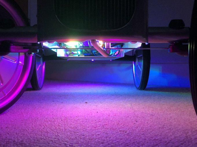
The result is rather satisfying:

Need more IMU.
Now controlling the brake lights and indicators using an accelerometer and gyro. pic.twitter.com/8KbTB0CFE3— Phil Howard (@Gadgetoid) June 28, 2020
And these realistic IMU-driven effects don’t stop me adding controls to re-enable R A I N B O W M O D E!

Rainbow light up Auto Union characature! Ready for your tiny vintage Grand Prix. pic.twitter.com/O3JFcH4UiE
— Phil Howard (@Gadgetoid) June 28, 2020
Anyway! I hope this has inspired you to get tinkering! If you’re looking for LEDs for your own project then I recommend APA102s (rather than WS2812) because they have a global brightness setting that allows you to dim the LEDs (and save battery) without reducing the spectrum of colours they can reproduce. They are also much, much simpler to drive since they use a clock/data two-wire signal rather than the very-timing-sensitive one-wire madness of the WS281X. You can grab some 60-pixels-per-meter strips for a pretty decent price from Pimoroni, these are a good balance between ALL THE LEDS and OUCH MY WALLET- https://shop.pimoroni.com/products/flexible-rgb-led-strip-dotstar-apa102-sk9822-compatible?variant=30260033224787